Description
Connection
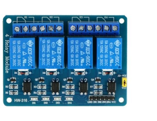
Connecting the power to the relay coil and the digital control signal is enough for proper operation. Leads are the standard strap goldpin pitch of 2.54 mm which enables connecting via connecting cables.
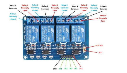
The relay has the following leads:
- VCC– the power of optical isolator.
- JD-VCC – the power of the relay coil, by default connected with the VCC through a jumper. To control the voltage of 3.3 V, disconnect the jumper, to the pin JD connect the power to the coil 5 V and to the VCC connect the voltage of 3.3 V.
- IN1, IN2, IN3, IN4 – control inputs of relays attached by the low state.
- GND– ground of the system, all GND leads are connected with each other.
- Connectors KF (ARK)– the relay’s contacts are connected in accordance with the pattern on board of the module.
Examples of usage
- Driver of light
- The driver of executors
- Switch for electric devices, including motors
Specification of Relay module 4 channels with optoisolation
- Supply voltage of a logic part: 3.3 V – 5 V
- Enabled by low-state
- Relay:
- Coil voltage: 5 V
- The maximum voltage of contacts: 250 V AC, 125 VAC
- The maximum output of the relay: DC 30V/10A, AC 250V/10A
- Maximum current: 10 A
- Optical isolation EL817
- Board size 75 x 50 mm
- Diameter of mounting holes: 3 mm
- Distance between holes: 68 mm and 43 mm


